|
With success in the preparation of quintet tetraradical, higher homologoues of the star-branched structures, hepta- and decaradicals, were prepared. The polyradicals were characterized using EPR spectroscopy and SQUID magnetometry [Technical Note 1]; magnetic moment for decaradical was also determined using Evans's NMR method [Technical Note 2].
At that time, the S = 7/2 and S = 5 were the highest spin values for organic polyradicals and the S = 5 was the highest value for an organic molecule, which included Iwamura's pentacarbene. This work was communicated in J. Am.Chem. Soc. in 1992.
- A. Rajca, S. Utamapanya, S. Thayumanavan, "Polyarylmethyl Octet (S = 7/2)
Heptaradical and Undecet (S = 5) Decaradical", J. Am. Chem. Soc., 1992, 114, 1884.
It seemed that extending the radical sites in the branched structure was a good approach to very high-spin molecules. Therefore, the dendritic polyarylmethyl polyradicals with 15 and 31 radical sites were in the plan. Syntheses of the precursors to these polyradical were carried out by the professor himself, soon after we were settled down at UNL. Unfortunately, the outcome was very disappointing. The S value for the dendritic polyarylmethyl with 31 sites for unpaired electrons (expected S = 31/2) was found to be much lower value of Saverage = 5/2 - 4/2.
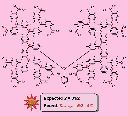
The polyarylmethyl with 15 sites for unpaired electrons (expected S = 5/2), for which the Saverage was found to be in the range 7/2 - 5/2, did not fare much better.
Upon careful analysis, it was determined that the problem might arise from
interruption(s) of spin couplings, due to failure to generate an unpaired electron or
twisting. In these polyradicals, there was only one pathway for spin coupling. If there was an interruption of the spin coupling (a defect) at one of the non-terminal spin sites, the ferromagnetic spin coupling will be interrupted, leading to a mixture of spin systems with low values of S. Therefore, average values of S for these radicals were much lower than expected.
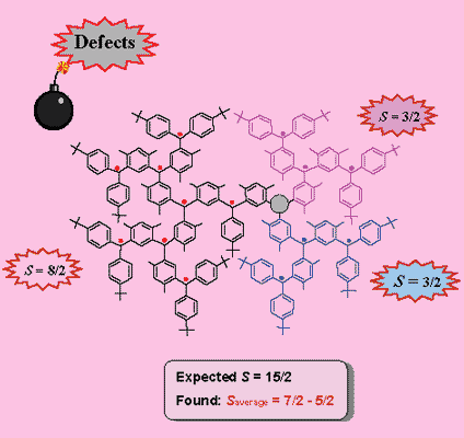
- A. Rajca, S. Utamapanya, "Toward Organic Synthesis of a Magnetic Particle: Dendritic Polyradicals with 15 and 31 Centers for Unpaired Electrons", J. Am. Chem. Soc., 1993, 115, 10688.
To solve the problem with the defects, we figured that least one more alternative pathways for spin coupling might help. With this hypothesis, macrocyclic π-systems with constrained conformations were considered as model building blocks. Hence, a calixarene-based macrocyclic polyradical was prepared.

- A. Rajca, S. Rajca, R. Padmakumar, "Calixarene-Based Macrocyclic Nonet (S = 4)
Octaradical and Its Acyclic Sextet (S = 5/2) Pentaradical Analogue", Angew. Chem. Int. Ed., 1994, 33, 2091.[Abstract]
- A. Rajca, S. Rajca, S. R. Desai, "Macrocyclic π-Conjugated Carbopolyanions and Polyradicals Based upon Calix[4]arene and Calix[3]arene Rings", J. Am. Chem. Soc., 1995, 117, 806.
This was another critical turning point of the Rajca group research. The success with the high-spin macrocyclic polyradical prompted us to pursue the syntheses of the macrocyclic 2-strand polyradical.
Technical Notes

UNDER CONSTRUCTION
Note 1: Preparation of Frozen Polyradical Samples for SQUID
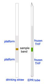
Preparation of frozen solution of polyradical for magnetic study using SQUID was very challenging. It was one of the most difficult and demanding experiments! The polyradicals must be kept at low temperature, preferably below -105 ºC, at all time. Furthermore, these polyradicals have quite low susceptibilities. To minimize background noise and signal distortion, it was desirable to have near mirror symmetry platforms above and below the samples (see MPMS Application Note 1014-201). To simulate the methods for mounting sample, as suggested for the MPMS by Quantum Design, we came up with the configuration of a frozen polyradical band embedded in between layers of frozen solvent inside an EPR tube.
During the early years, the polyradical prepared were not with as high spin as those prepared lately. As the sizes and the spin values increased, the polyradicals became more susceptible to thermal decomposition. Therefore, preparation method for these polyradicals had to be modified, to prevent thermal decomposition and to accommodate small amounts of the precursor polyethers.
For the very first experiment we carried out in early 1990s, a typical procedure was as follow:
- Step 1: Generation of polyanion
Polyanion was prepared in a glovebox. Simply, the corresponding polyether sample was weighed in a small screw cap vial, THF solvent was added, and then a small, shiny, Li piece was dropped into the well-stirred solution. Pink (or red) color of the polyanion appeared almost instantly; within a few minutes, the solution turned deep dark red color. It was very important that the generation of polyanion started well, i.e. the red color must appear within a few minutes after adding the metal. Typically, this was achieved with the use of high purity reagents: starting polyether, THF solvent, and a shiny Li (high in Na) piece. Good stirring must be maintained all times until completion of the reaction
- Step 2: Oxidation Vessel and Transferring of Polyanions
First, add about 0.4 mL of THF into the oxidation vessel and pour it over into the EPR tube; the level of THF in the tube was about 6 cm. Subsequently, transfer the polyanion into the oxidation vessel, using a long needle and a glass syringe. Rinse the vial and the syringe with a small amount of THF.
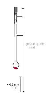
Add a stir bar, close the stopcock and take the oxidation vessel out to a vacuum line.
- Step 3: Oxidation
Solution of the polyanion was cooled to -95 ºC, in acetone/liquid N2 (LN2) bath). In the meantime, solid I2 was weighed on analytical balance. It was a bit tricky to scoop away the desired amount of I2, as it was important to weigh approximate amount I2 to the molar equivalence required for the oxidation reaction. (Typically, it was better to have slightly more.) The I2 solid was added under the stream of Ar gas. In several minutes, color of the solution turned from red to either yellow or green (or a sequence of colors, as in the case of some polyradicals). For the oxidation reaction of each polyanion, we learned the sequences of the change in colors and colors of the polyradicals; EPR experiments were quite helpful in this regard. Even that, for each new polyradical, it was always guessing and repeating, in order to obtain the best end product approaching correct value of S. Quite often, due to inaccuracy of weights of either polyether or I2, amount of the first added I2 did not give color expected for the polyradical; in such a case, a small, sub-milligram crystal of I2 solid was added into the reaction mixture. Scooping a half-milligram of I2 was even more of an intractable task!
- Step 4: Making Bottom Layer Frozen Solvent (THF)
Just slowly immersed the EPR tube into LN2.
- Step 5: Transferring polyradical solution onto the frozen solvent layer
This was done in a large EtOH/LN2 slush bath. The bath was prepared in a large dewar as follow. First, filled up about half of the dewar with EtOH; while constantly stirring with a wooden rod, slowly pour small amount of LN2 into the dewar. Work on it carefully not to allow EtOH to boil up out of the dewar nor to from crust. Keep adding EtOH and LN2, forming viscous mixture (slush) with some solid EtOH, to the level of about an inch below the rim of the dewar.
Both the reaction vessel, including the EPR tube, was quickly immersed into the EtOH/LN2 slush bath, having the slush cover up to a couple, or so, inches below the stopcock. Allow just enough time for temperature equilibration. If the solution of polyradical was kept too long in the slush bath, it might freeze and had to be melted at -95 ºC in acetone/LN2 bath. After that, small amount of LN2 was poured over the top of the slush, to partially freeze the slush, holding it in place. A foam cap was placed over the top of the dewar and the dewar was quickly tilted, with the hope that part of the polyradical sample would move over into the sample tube compartment. Obviously, we could not see what was going on inside the slush bath; we hoped to be lucky to transfer just right amount of polyradical solution to form about 3-5 mm high sample band. As we know, luck was not so common; so we failed many times in this process. It was not too bad with too little sample; we could try to pour more. In any case, narrow sample band was preferred for the SQUID. However, if there was too much sample, it could not be removed from the sample tube and we end up with too large sample band, not suitable for SQUID measurement. The whole experiment failed. Worse, because of the movement, sample tube broke inside the bath! Once there was good amount of polyradical sample inside the EPR tube, which was typically viscous solution on the wall of the tube, a sample band was formed by repetitive application of temperature gradients to the wall of the tube. Temperature gradient was applied by rubbing the tube with rubber glove, i.e. basically, with glove on, rubbing the tube with the thumb and the index fingers. Care must be taken not to warm up the sample; the vessel was immersing into the slush bath every few second, alternating with the rubbing process. Slowly, moving the polyradical onto the frozen THF, forming the sample band.
- Step 6: Making frozen solvent (THF) top layer in the sample tube
Once we had the sample band, this step was an easy one. The reaction vessel was withdrawn from the slush bath and the oxidation compartment, which contained the remaining amount of the radical sample, was quickly placed into the acetone/LN2; the EPR tube was placed into LN2. With the EPR tube immersed in LN2, THF was slowly vacuum transferred onto the sample band, to form about 6.5-cm high band of frozen THF.
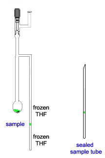
- Step 7: Seal the sample tube
The final step was also a very nervous one. Sealing the quartz tube just above liquid nitrogen dewar filled with LN2.
Transferring of polyradical solution into the EPR tube was an obstacle to the success of most experiments. Without being able to see inside, it was very difficult to transfer right amount of the radical sample into the EPR tube. Many times we ended up empty handed: either too much sample was transferred or the tube broke inside the dewar. We even got a tall dewar with a narrow strip of small viewing windows, a much smaller and lighter than the the one used before; however, the outcome was not much different. Frustration had set in and prompted us to observe the experiment more carefully. Simple enough, the EtOH/LN2 slush was thick viscous, gluey; it coated around the vessel and sticked onto it. This would allow the vessel to be pulled out from the slush bath for a few seconds, without significantly warming up the polyradical and allowing for better control of the critical transfer step. It appeared that it took only a few seconds to transfer sample over to the ESR compartment. This was much better. However, we found that, with the rapid movement of a few seconds to pour the radical sample, it still was not easy to control the amount of solution that went over into the sample compartment. We made a minor modification by making a narrow bore (capillary) tube above the EPR tube. In such case, the polyradical solution would fill in the capillary, not moving further into the ESR tube. This allow us to control the portion of sample to be moved into the sample tube; the rest of it was moved back to the oxidation compartment.
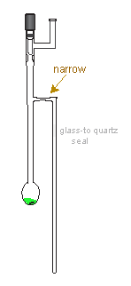
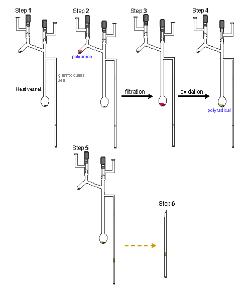
As the we continued to make larger polyethers, syntheses were much more difficult. We had to work with much less amount of the sample. The typical experiment involved very small amount of polyether (ca. 1 mg). With this, extreme care must be taken to prevent any failure, in particular from moisture. For most polyradicals, we routinely carried out EPR experiments before preparation of sample for SQUID. So, we learned a lot about oxidation process of each polyradical sample. During the process, we made a few critical modifications. First, a new reaction vessel design with compartment for polyanion generation and a frit for filtration. Second, the reaction vessel was heated to 200 ºC, using heating tape, overnight on vacuum line before used. Third, instead of the EPR tube for sample compartment, the vessel was made with a SQUID tube. With the arrival of Steve Anderson (now at Mayo Clinic), was able to custom made the SQUID tube, an opened end EPR tube with a thin, flat, quartz layer in the middle. Without having to make the sample band in between the frozen THF was a big step forward. Not only that it simplified the sample preparation for SQIUD, it was also better for the SQUID instrument. Many times, when we pulled out sample tubes from the SQUID, we found broken tubes, without knowing the cause. Big mess with large amount of THF solvent inside the SQUID sample chamber!
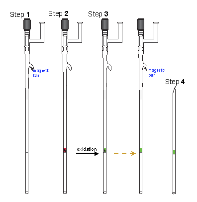
So, the modified procedure is as follow:
- Step 1: Heating the Vessel on Vacuum line
The vessel was heated using heating tape on vacuum line to 200 ºC for several hours. Occasionally, the vacuum line was heated using a heat gun.
- Step 2: Generation of Polyanions
After the heating step was completed, polyether sample was loaded, under flow of Ar, into the compartment for polyanion generation. The vessel was then brought to the glovebox and a small Li piece or a small drop of Na/K alloy, was placed in the top part reaction vessel. After that, the vessel was brought back onto the vacuum line; THF solvent was vacuum transferred to dissolve the sample. After that, the alkaline metal was dropped into the well-stirred solution, to start the polyanion generation.
- Step 3: Filtration
After the generation of polyanion was completed, the solution was filtered through the frit into the compartment for oxidation.
- Step 4: Oxidation
The oxidation process proceeded as described before.
- Step 5: Transferring of the Polyradical into the SQUID tube
Before putting the vessel into the slush bath, put a cap onto the bottom SQUID tube.
- Step 6: Seal the sample tube
Another very important modification was the addition of I2. With very small scale oxidation, addition of an equivalent amount of solid I2 by weight was a problem. As we learned the sequence of the color changes during the oxidation of each polyradical, we used the colors as an indicator. Since it was not accurate to weigh very small amount of solid I2, we vacuum transferred I2 vapor to the polyanion. At the beginning, we used this method to complement the addition of solid I2, when it failed to produce the color of radical. Later on, we used it for every small scale reactions. To do this, the reaction vessel was removed from the cold bath and immersed into LN2, with the level just above that of for the polyradical solution. I2 was vacuum transferred to the top of the frozen polyradical solution. After that, the reaction vessel was return back to the cold bath and the I2 was dissolved into the reaction mixture by stirring. The I2 transfers were repeated until the endpoint for the reaction was attained.
Yet, for very small scale reaction, we further modified the procedure. First, the the oxidation compartment was eliminated, so the oxidation was done directly in SQUID tube. Second, the polyether was heated in the reaction vessel before used. With this setup, polyether was loaded into the reaction compartment of the vessel and evacuated on the vacuum line. While the sample was heated in an oil bath at about 60 ºC, the rest of the vessel, i.e. the frit and SQUID tube, was heated to above 200 ºC, using heating tape. After the heat treatment (topically more than one day), it was taken to the glovebox, where a small Li piece or a drop of Na/K alloy was suspended on top of the reaction vessel. Back on vacuum line, THF solvent was vacuum transferred into the reaction compartment, the metal piece was dropped into the solution to start the polyanion generation. Third, temperature of the polyanion generation was controlled at about 10 ºC, using a cooled air bath (stream of air flow through an ice bath). After the generation of polyanion was finished, the solution was filtered through the frit into the SQUID tube. Oxidation was done by vacuum transfer of I2 vapor into the sample compartment. Each postion of I2 was dissolved by tapping with finger on the tube.
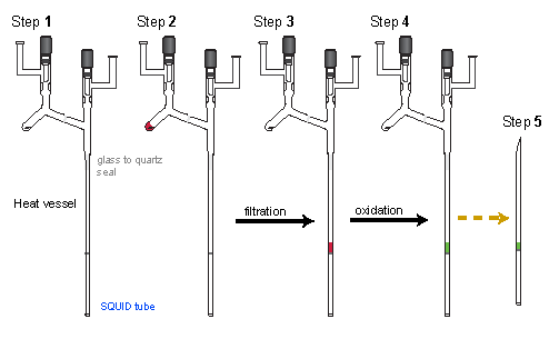
Photo below shows the experimental setup for low temperature polyanion generation. [note: however, this was the preparation for the SANS experiment, so the sample compartment used was the cylindrical UV cell, instead of the SQUID tube.]

The latest modification was for preparation of network polyradical for SQUID study. Now, everything was done in one tube!
Note 2: Determination of Magnetic Moments of Polyradical by Evan's NMR Method
... more detail coming soon!
|

